Contents Page
Foreword........................................................................................................................................ iv
Introduction..................................................................................................................................... v
Scope.................................................................................................................................. 1
Normative references.......................................................................................................... 1
Terms, definitions and abbreviated terms........................................................................... 1
Network layer overview....................................................................................................... 3
General................................................................................................................................ 3
Services provided by network layer to higher layers........................................................... 3
Internal operation of network layer...................................................................................... 4
Network layer services........................................................................................................ 5
General................................................................................................................................ 5
Specification of network layer service primitives................................................................ 6
Service data unit specification............................................................................................ 8
Network layer protocol....................................................................................................... 12
Protocol functions............................................................................................................. 12
Single frame transmission................................................................................................. 12
Multiple frame transmission.............................................................................................. 12
Network layer protocol data units...................................................................................... 15
Protocol control information specification........................................................................ 16
Maximum number of FC.Wait frame transmissions (N_WFTmax)...................................... 23
Network layer timing.......................................................................................................... 23
Interleaving of messages................................................................................................... 27
Data link layer usage......................................................................................................... 27
Data link layer interface services....................................................................................... 27
Data link layer service parameters..................................................................................... 28
Mapping of the N_PDU fields............................................................................................. 28
CAN frame Data Length Code (DLC).................................................................................. 30
Annex A (informative) Use of normal fixed and mixed addressing with data link layer according to
SAE J1939.......................................................................................................................... 32
Bibliography ............... 35
Foreword
ISO (the International Organization for Standardization) is a worldwide federation of national standards bodies (ISO member bodies). The work of preparing International Standards is normally carried out through ISO technical committees. Each member body interested in a subject for which a technical committee has been established has the right to be represented on that committee. International organizations, governmental and non-governmental, in liaison with ISO, also take part in the work. ISO collaborates closely with the International Electrotechnical Commission (IEC) on all matters of electrotechnical standardization.
International Standards are drafted in accordance with the rules given in the ISO/IEC Directives, Part 2.
The main task of technical committees is to prepare International Standards. Draft International Standards adopted by the technical committees are circulated to the member bodies for voting. Publication as an International Standard requires approval by at least 75 % of the member bodies casting a vote.
Attention is drawn to the possibility that some of the elements of this document may be the subject of patent rights. ISO shall not be held responsible for identifying any or all such patent rights.
ISO 15765-2 was prepared by Technical Committee ISO/TC 22, Road vehicles, Subcommittee SC 3,
Electrical and electronic equipment.
ISO 15765 consists of the following parts, under the general title Road vehicles — Diagnostics on Controller Area Networks (CAN):
Part 1: General information
Part 2: Network layer services
Part 3: Implementation of unified diagnostic services (UDS on CAN)
Part 4: Requirements for emissions-related systems
Introduction
This part of ISO 15765 has been established in order to define common requirements for vehicle diagnostic systems implemented on a Controller Area Network (CAN) communication link, as specified in ISO 11898. Although primarily intended for diagnostic systems, it also meets requirements from other CAN-based systems needing a network layer protocol.
To achieve this, it is based on the Open Systems Interconnection (OSI) Basic Reference Model specified in ISO/IEC 7498 and ISO/IEC 10731, which structures communication systems into seven layers. When mapped on this model, the services specified by ISO 15765 are divided into
unified diagnostic services (layer 7), specified in ISO 15765-3,
network layer services (layer 3), specified in this part of ISO 15765,
CAN services (layers 1 and 2), specified in ISO 11898, in accordance with Table
The application layer services covered by ISO 15765-3 have been defined in compliance with diagnostic services established in ISO 14229-1 and ISO 15031-5, but are not limited to use only with them. ISO 15765-3 is also compatible with most diagnostic services defined in national standards or vehicle manufacturer's specifications.
The network layer services covered by this part of ISO 15765 have been defined to be independent of the physical layer implemented, and a physical layer is only specified for legislated OBD.
For other application areas, ISO 15765 can be used with any CAN physical layer.
Table 1 — Enhanced and legislated OBD diagnostic specifications applicable to the OSI layers
Open Systems Interconnection (OSI) layers
Vehicle manufacturer enhanced diagnostics
Legislated on-board diagnostics (OBD)
Diagnostic application
User defined
ISO 15031-5
Application layer
ISO 15765-3
ISO 15031-5
Presentation layer
N/A
N/A
Session layer
ISO 15765-3
N/A
Transport layer
N/A
N/A
Network layer
ISO 15765-2
ISO 15765-4
Data link layer
ISO 11898-1
ISO 15765-4
Physical layer
User defined
ISO 15765-4
Road vehicles — Diagnostics on Controller Area Networks (CAN) —
Part 2: Network layer services
1 Scope
This part of ISO 15765 specifies a network protocol tailored to meet the requirements of CAN-based vehicle network systems on controller area networks as specified in ISO 11898. It has been defined in accordance with the diagnostic services established in ISO 14229-1 and ISO 15031-5, but is not limited to use with them, and is also compatible with most other communication needs for in-vehicle networks. The protocol specifies an unconfirmed communication.
2 Normative references
The following referenced documents are indispensable for the application of this document. For dated references, only the edition cited applies. For undated references, the latest edition of the referenced document (including any amendments) applies.
ISO 11898-1, Road vehicles — Controller area network (CAN) — Part 1: Data link layer and physical signalling
ISO/IEC 7498 (all parts), Information technology — Open Systems Interconnection — Basic Reference Model
3 Terms, definitions and abbreviated terms
For the purposes of this document, the terms and definitions given in ISO 7498, and the following abbreviated terms, apply.
BS block size
CF consecutive frame
confirm confirmation service primitive
ECU electronic control unit
FC flow control
FF first frame
FF_DL first frame data length
FS flow status
indication indication service primitive
Mtype message type
N_AE network address extension
N_AI address information
N_Ar network layer timing parameter Ar
N_As network layer timing parameter As
N_Br network layer timing parameter Br
N_Bs network layer timing parameter Bs N_ChangeParameter network layer service name
N_Cr network layer timing parameter Cr
N_Cs network layer timing parameter Cs
N_Data network data
N_PCI network protocol control information
N_PCItype network protocol control information type
N_PDU network protocol data unit
N_SA network source address
N_SDU network service data unit
N_TA network target address
N_TAtype network target address type
N_USData network layer unacknowledged segmented data transfer service name NWL network layer
request request service primitive
receiver
sender
SF single frame
SF_DL single frame data length
SN sequence number
STmin separation time min.
4 Network layer overview 4.1 General
This clause describes the overall functionality of the network layer. This part of ISO 15765 specifies an unconfirmed network layer communication protocol for the exchange of data between network nodes, e.g. from ECU to ECU, or between external test equipment and an ECU. If the data to be transferred do not fit into a single CAN frame, a segmentation method is provided.
In order to describe the function of the network layer, services provided to higher layers and the internal operation of the network layer have to be considered.
4.2 Services provided by network layer to higher layers
The service interface defines a set of services that are needed to access the functions offered by the network layer, i.e. transmission/reception of data and setting of protocol parameters.
Two types of services are defined.
a) Communication services
These services, of which the following are defined, enable the transfer of up to 4 095 bytes of data.
1) N_USData.request
This service is used to request the transfer of data. If necessary, the network layer segments the data.
2) N_USData_FF.indication
This service is used to signal the beginning of a segmented message reception to the upper layer.
3) N_USData.indication
This service is used to provide received data to the higher layers.
4) N_USData.confirm
This service confirms to the higher layers that the requested service has been carried out (successfully or not).
b) Protocol parameter setting services
These services, of which the following are defined, enable the dynamic setting of protocol parameters.
1) N_ChangeParameter.request
This service is used to request the dynamic setting of specific internal parameters.
2) N_ChangeParameter.confirm
This service confirms to the upper layer that the request to change a specific protocol has been carried out (successfully or not).
4.3 Internal operation of network layer
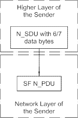
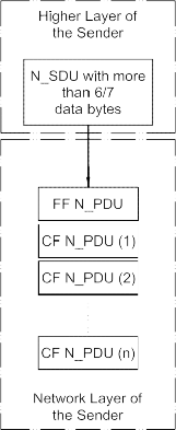
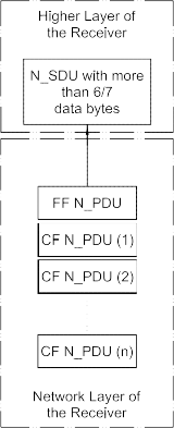
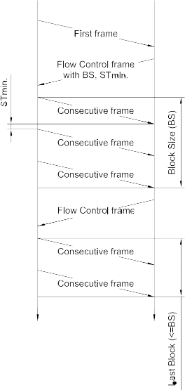
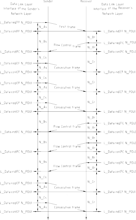
The internal operation of the network layer provides methods for segmentation, transmission with flow control, and reassembly. The main purpose of the network layer is to transfer messages that might or might not fit in a single CAN frame. Messages that do not fit into a single CAN frame are segmented into multiple parts, where each can be transmitted in a CAN frame.
Figure 1 shows an example of an unsegmented message transmission. sender Receiver
Figure 1 — Example of unsegmented message
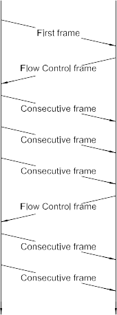
Figure 2 shows an example of a segmented message transmission.sender Receiver
Figure 2 — Example of segmented message
Flow control is used to adjust the sender to the network layer capabilities of the receiver. This flow control scheme allows the use of diagnostic gateways and sub-networks.
ISO 15765 specifies three different addressing formats: normal, extended and mixed.
5 Network layer services
5.1 General
All network layer services have the same general structure. To define the services, three types of service primitives are specified:
a service request primitive, used by higher communication layers or the application to pass control information and data required to be transmitted to the network layer;
a service indication primitive, used by the network layer to pass status information and received data to upper communication layers or the application;
a service confirmation primitive used by the network layer to pass status information to higher communication layers or the
This service specification does not specify an application programming interface, but only a set of service primitives that are independent of any implementation.
All network layer services have the same general format. Service primitives are written in the form:
service_name.type (
parameter A, parameter B, parameter C,
...
)
where “service_name” is the name of the service, e.g. N_USData, “type” indicates the type of the service primitive, and “parameter A, parameter B, parameter C, ...” are the N_SDU as a list of values passed by the service primitive.
The service primitives define how a service user (e.g. diagnostic application) cooperates with a service provider (e.g. network layer). The following service primitives are specified in this International Standard: request, indication and confirm.
Using the service primitive request (service_name.request) a service user requests a service from the service
Using the service primitive indication (service_name.indication), the service provider informs a service user about an internal event of the network layer or the service request of a peer protocol layer entity service
With the service primitive confirm (service_name.confirm) the service provider informs the service user about the result of a preceding service request of the service
5.2 Specification of network layer service primitives
5.2.1 N_USData.request
The service primitive requests transmission of <MessageData> with <Length> bytes from the sender to the receiver peer entities identified by the address information in N_SA, N_TA, N_TAtype, and N_AE 1) (see 5.3 for parameter definition).
Each time the N_USData.request service is called, the network layer shall signal the completion (or failure) of the message transmission to the service user by means of the issuing of an N_USData.confirm service call:
N_USData.request (
Mtype N_SA N_TA
N_TAtype N_AE 1)
<MessageData>
<Length>
)
5.2.2 N_USData.confirm
The N_USData.confirm service is issued by the network layer. The service primitive confirms the completion of an N_USData.request service identified by the address information in N_SA, N_TA, N_TAtype, and N_AE 1). The parameter <N_Result> provides the status of the service request (see 5.3 for parameter definition).
N_USData.confirm (
Mtype N_SA N_TA
N_TAtype N_AE1)
<N_Result>
)
5.2.3 N_USData.indication
The N_USData_FF.indication service is issued by the network layer. The service primitive indicates to the adjacent upper layer the arrival of a first frame (FF) of a segmented message received from a peer protocol entity, identified by the address information in N_SA, N_TA, N_TAtype, and N_AE 1) (see 5.3 for parameter definition). This indication shall take place upon reception of the first frame (FF) of a segmented message.
N_USData_FF.indication (
Mtype N_SA N_TA
N_TAtype N_AE1)
<Length>
)
The N_USData_FF.indication service shall always be followed by an N_USData.indication service call from the network layer, indicating the completion (or failure) of the message reception.1) Optional
An N_USData_FF.indication service call shall only be issued by the network layer if a correct first frame (FF) message segment has been received.
If the network layer detects any type of error in a first frame (FF), then the message shall be ignored by the network layer and no N_USData_FF.indication shall be issued to the adjacent upper layer.
If the network layer receives a first frame (FF) with a data length value (FF_DL) that is greater than the available receiver buffer size, then this shall be considered as an error condition and no N_USData_FF.indication shall be issued to the adjacent upper layer.
5.2.4 N_USData.indication
The N_USData.indication service is issued by the network layer. The service primitive indicates <N_Result> events and delivers <MessageData> with <Length> bytes received from a peer protocol entity identified by the address information in N_SA, N_TA, N_TAtype, and N_AE 2) to the adjacent upper layer (see 5.3 for parameter definition).
The parameters <MessageData> and <Length> are only valid if <N_Result> equals N_OK.
N_USData.indication (
Mtype N_SA N_TA
N_TAtype N_AE2)
<MessageData>
<Length>
<N_Result>
)
The N_USData.indication service call is issued after the reception of a single frame (SF) message or as an indication of the completion (or failure) of a segmented message reception.
If the network layer detects any type of error in a single frame (SF), then the message shall be ignored by the network layer and no N_USData.indication shall be issued to the adjacent upper layer.
5.2.5 N_ChangeParameters.request
The service primitive is used to request the change of an internal parameter’s value on the local protocol entity. The <Parameter_Value> is assigned to the <Parameter> (see 5.3 for parameter definition).
A parameter change is always possible, except after reception of the first frame (N_USData_FF.indication) and until the end of the reception of the corresponding message (N_USData.indication).
N_ChangeParameter.request (
Mtype N_SA N_TA
N_TAtype N_AE2)
<Parameter>
<Parameter_Value>
)
This is an optional service that can be replaced by implementation of fixed parameter values.
5.2.6 N_ChangeParameter.confirm
The service primitive confirms the completion of an N_ChangeParameter.Confirmation service applying to a message identified by the address information in N_SA, N_TA, N_TAtype, and N_AE 3) (see 5.3 for parameter definition).
N_ChangeParameter.confirm (
Mtype N_SA N_TA
N_TAtype N_AE3)
<Parameter>
<Result_ChangeParameter>
)
5.3 Service data unit specification 5.3.1 Mtype, Message type
Type: enumeration
Range: diagnostics, remote diagnostics
Description: The parameter Mtype shall be used to identify the type and range of address information parameters included in a service call. This part of ISO 15765 specifies a range of two values for this parameter. The intention is that users of the document can extend the range of values by specifying other types and combinations of address information parameters to be used with the network layer protocol specified in this document. For each such new range of address information, a new value for the Mtype parameter shall be specified to identify the new address information.
If Mtype = diagnostics, then the address information N_AI shall consist of the parameters N_SA, N_TA, and
If Mtype = remote diagnostics, then the address information N_AI shall consist of the parameters N_SA, N_TA, N_TAtype, and
5.3.2 N_AI, Address Information
5.3.2.1 N_AI description
These parameters refer to addressing information. As a whole, the N_AI parameters are used to identify the source address (N_SA), target address (N_TA) of message senders and recipients as well as the communication model for the message (N_TAtype) and the optional address extension (N_AE).
5.3.2.2 N_SA, Network Source Address Type: 1 byte unsigned integer value Range: 00-FF hex
Description: The N_SA parameter shall be used to encode the sending network layer protocol entity.
5.3.2.3 N_TA, Network Target Address Type: 1 byte unsigned integer value Range: 00-FF hex
Description: The N_TA parameter shall be used to encode the receiving network layer protocol entity.
5.3.2.4 N_TAtype, Network Target Address type
Type: enumeration Range: physical, functional
Description: The parameter N_TAtype is an extension to the N_TA parameter. It shall be used to encode the communication model used by the communicating peer entities of the network layer....
Foreword........................................................................................................................................ iv
Introduction..................................................................................................................................... v
Scope.................................................................................................................................. 1
Normative references.......................................................................................................... 1
Terms, definitions and abbreviated terms........................................................................... 1
Network layer overview....................................................................................................... 3
General................................................................................................................................ 3
Services provided by network layer to higher layers........................................................... 3
Internal operation of network layer...................................................................................... 4
Network layer services........................................................................................................ 5
General................................................................................................................................ 5
Specification of network layer service primitives................................................................ 6
Service data unit specification............................................................................................ 8
Network layer protocol....................................................................................................... 12
Protocol functions............................................................................................................. 12
Single frame transmission................................................................................................. 12
Multiple frame transmission.............................................................................................. 12
Network layer protocol data units...................................................................................... 15
Protocol control information specification........................................................................ 16
Maximum number of FC.Wait frame transmissions (N_WFTmax)...................................... 23
Network layer timing.......................................................................................................... 23
Interleaving of messages................................................................................................... 27
Data link layer usage......................................................................................................... 27
Data link layer interface services....................................................................................... 27
Data link layer service parameters..................................................................................... 28
Mapping of the N_PDU fields............................................................................................. 28
CAN frame Data Length Code (DLC).................................................................................. 30
Annex A (informative) Use of normal fixed and mixed addressing with data link layer according to
SAE J1939.......................................................................................................................... 32
Bibliography ............... 35
Foreword
ISO (the International Organization for Standardization) is a worldwide federation of national standards bodies (ISO member bodies). The work of preparing International Standards is normally carried out through ISO technical committees. Each member body interested in a subject for which a technical committee has been established has the right to be represented on that committee. International organizations, governmental and non-governmental, in liaison with ISO, also take part in the work. ISO collaborates closely with the International Electrotechnical Commission (IEC) on all matters of electrotechnical standardization.
International Standards are drafted in accordance with the rules given in the ISO/IEC Directives, Part 2.
The main task of technical committees is to prepare International Standards. Draft International Standards adopted by the technical committees are circulated to the member bodies for voting. Publication as an International Standard requires approval by at least 75 % of the member bodies casting a vote.
Attention is drawn to the possibility that some of the elements of this document may be the subject of patent rights. ISO shall not be held responsible for identifying any or all such patent rights.
ISO 15765-2 was prepared by Technical Committee ISO/TC 22, Road vehicles, Subcommittee SC 3,
Electrical and electronic equipment.
ISO 15765 consists of the following parts, under the general title Road vehicles — Diagnostics on Controller Area Networks (CAN):
Part 1: General information
Part 2: Network layer services
Part 3: Implementation of unified diagnostic services (UDS on CAN)
Part 4: Requirements for emissions-related systems
Introduction
This part of ISO 15765 has been established in order to define common requirements for vehicle diagnostic systems implemented on a Controller Area Network (CAN) communication link, as specified in ISO 11898. Although primarily intended for diagnostic systems, it also meets requirements from other CAN-based systems needing a network layer protocol.
To achieve this, it is based on the Open Systems Interconnection (OSI) Basic Reference Model specified in ISO/IEC 7498 and ISO/IEC 10731, which structures communication systems into seven layers. When mapped on this model, the services specified by ISO 15765 are divided into
unified diagnostic services (layer 7), specified in ISO 15765-3,
network layer services (layer 3), specified in this part of ISO 15765,
CAN services (layers 1 and 2), specified in ISO 11898, in accordance with Table
The application layer services covered by ISO 15765-3 have been defined in compliance with diagnostic services established in ISO 14229-1 and ISO 15031-5, but are not limited to use only with them. ISO 15765-3 is also compatible with most diagnostic services defined in national standards or vehicle manufacturer's specifications.
The network layer services covered by this part of ISO 15765 have been defined to be independent of the physical layer implemented, and a physical layer is only specified for legislated OBD.
For other application areas, ISO 15765 can be used with any CAN physical layer.
Table 1 — Enhanced and legislated OBD diagnostic specifications applicable to the OSI layers
Open Systems Interconnection (OSI) layers
Vehicle manufacturer enhanced diagnostics
Legislated on-board diagnostics (OBD)
Diagnostic application
User defined
ISO 15031-5
Application layer
ISO 15765-3
ISO 15031-5
Presentation layer
N/A
N/A
Session layer
ISO 15765-3
N/A
Transport layer
N/A
N/A
Network layer
ISO 15765-2
ISO 15765-4
Data link layer
ISO 11898-1
ISO 15765-4
Physical layer
User defined
ISO 15765-4
Road vehicles — Diagnostics on Controller Area Networks (CAN) —
Part 2: Network layer services
1 Scope
This part of ISO 15765 specifies a network protocol tailored to meet the requirements of CAN-based vehicle network systems on controller area networks as specified in ISO 11898. It has been defined in accordance with the diagnostic services established in ISO 14229-1 and ISO 15031-5, but is not limited to use with them, and is also compatible with most other communication needs for in-vehicle networks. The protocol specifies an unconfirmed communication.
2 Normative references
The following referenced documents are indispensable for the application of this document. For dated references, only the edition cited applies. For undated references, the latest edition of the referenced document (including any amendments) applies.
ISO 11898-1, Road vehicles — Controller area network (CAN) — Part 1: Data link layer and physical signalling
ISO/IEC 7498 (all parts), Information technology — Open Systems Interconnection — Basic Reference Model
3 Terms, definitions and abbreviated terms
For the purposes of this document, the terms and definitions given in ISO 7498, and the following abbreviated terms, apply.
BS block size
CF consecutive frame
confirm confirmation service primitive
ECU electronic control unit
FC flow control
FF first frame
FF_DL first frame data length
FS flow status
indication indication service primitive
Mtype message type
N_AE network address extension
N_AI address information
N_Ar network layer timing parameter Ar
N_As network layer timing parameter As
N_Br network layer timing parameter Br
N_Bs network layer timing parameter Bs N_ChangeParameter network layer service name
N_Cr network layer timing parameter Cr
N_Cs network layer timing parameter Cs
N_Data network data
N_PCI network protocol control information
N_PCItype network protocol control information type
N_PDU network protocol data unit
N_SA network source address
N_SDU network service data unit
N_TA network target address
N_TAtype network target address type
N_USData network layer unacknowledged segmented data transfer service name NWL network layer
request request service primitive
receiver
sender
SF single frame
SF_DL single frame data length
SN sequence number
STmin separation time min.
4 Network layer overview 4.1 General
This clause describes the overall functionality of the network layer. This part of ISO 15765 specifies an unconfirmed network layer communication protocol for the exchange of data between network nodes, e.g. from ECU to ECU, or between external test equipment and an ECU. If the data to be transferred do not fit into a single CAN frame, a segmentation method is provided.
In order to describe the function of the network layer, services provided to higher layers and the internal operation of the network layer have to be considered.
4.2 Services provided by network layer to higher layers
The service interface defines a set of services that are needed to access the functions offered by the network layer, i.e. transmission/reception of data and setting of protocol parameters.
Two types of services are defined.
a) Communication services
These services, of which the following are defined, enable the transfer of up to 4 095 bytes of data.
1) N_USData.request
This service is used to request the transfer of data. If necessary, the network layer segments the data.
2) N_USData_FF.indication
This service is used to signal the beginning of a segmented message reception to the upper layer.
3) N_USData.indication
This service is used to provide received data to the higher layers.
4) N_USData.confirm
This service confirms to the higher layers that the requested service has been carried out (successfully or not).
b) Protocol parameter setting services
These services, of which the following are defined, enable the dynamic setting of protocol parameters.
1) N_ChangeParameter.request
This service is used to request the dynamic setting of specific internal parameters.
2) N_ChangeParameter.confirm
This service confirms to the upper layer that the request to change a specific protocol has been carried out (successfully or not).
4.3 Internal operation of network layer
The internal operation of the network layer provides methods for segmentation, transmission with flow control, and reassembly. The main purpose of the network layer is to transfer messages that might or might not fit in a single CAN frame. Messages that do not fit into a single CAN frame are segmented into multiple parts, where each can be transmitted in a CAN frame.
Figure 1 shows an example of an unsegmented message transmission. sender Receiver
Figure 1 — Example of unsegmented message
Figure 2 shows an example of a segmented message transmission.sender Receiver
Figure 2 — Example of segmented message
Flow control is used to adjust the sender to the network layer capabilities of the receiver. This flow control scheme allows the use of diagnostic gateways and sub-networks.
ISO 15765 specifies three different addressing formats: normal, extended and mixed.
5 Network layer services
5.1 General
All network layer services have the same general structure. To define the services, three types of service primitives are specified:
a service request primitive, used by higher communication layers or the application to pass control information and data required to be transmitted to the network layer;
a service indication primitive, used by the network layer to pass status information and received data to upper communication layers or the application;
a service confirmation primitive used by the network layer to pass status information to higher communication layers or the
This service specification does not specify an application programming interface, but only a set of service primitives that are independent of any implementation.
All network layer services have the same general format. Service primitives are written in the form:
service_name.type (
parameter A, parameter B, parameter C,
...
)
where “service_name” is the name of the service, e.g. N_USData, “type” indicates the type of the service primitive, and “parameter A, parameter B, parameter C, ...” are the N_SDU as a list of values passed by the service primitive.
The service primitives define how a service user (e.g. diagnostic application) cooperates with a service provider (e.g. network layer). The following service primitives are specified in this International Standard: request, indication and confirm.
Using the service primitive request (service_name.request) a service user requests a service from the service
Using the service primitive indication (service_name.indication), the service provider informs a service user about an internal event of the network layer or the service request of a peer protocol layer entity service
With the service primitive confirm (service_name.confirm) the service provider informs the service user about the result of a preceding service request of the service
5.2 Specification of network layer service primitives
5.2.1 N_USData.request
The service primitive requests transmission of <MessageData> with <Length> bytes from the sender to the receiver peer entities identified by the address information in N_SA, N_TA, N_TAtype, and N_AE 1) (see 5.3 for parameter definition).
Each time the N_USData.request service is called, the network layer shall signal the completion (or failure) of the message transmission to the service user by means of the issuing of an N_USData.confirm service call:
N_USData.request (
Mtype N_SA N_TA
N_TAtype N_AE 1)
<MessageData>
<Length>
)
5.2.2 N_USData.confirm
The N_USData.confirm service is issued by the network layer. The service primitive confirms the completion of an N_USData.request service identified by the address information in N_SA, N_TA, N_TAtype, and N_AE 1). The parameter <N_Result> provides the status of the service request (see 5.3 for parameter definition).
N_USData.confirm (
Mtype N_SA N_TA
N_TAtype N_AE1)
<N_Result>
)
5.2.3 N_USData.indication
The N_USData_FF.indication service is issued by the network layer. The service primitive indicates to the adjacent upper layer the arrival of a first frame (FF) of a segmented message received from a peer protocol entity, identified by the address information in N_SA, N_TA, N_TAtype, and N_AE 1) (see 5.3 for parameter definition). This indication shall take place upon reception of the first frame (FF) of a segmented message.
N_USData_FF.indication (
Mtype N_SA N_TA
N_TAtype N_AE1)
<Length>
)
The N_USData_FF.indication service shall always be followed by an N_USData.indication service call from the network layer, indicating the completion (or failure) of the message reception.1) Optional
An N_USData_FF.indication service call shall only be issued by the network layer if a correct first frame (FF) message segment has been received.
If the network layer detects any type of error in a first frame (FF), then the message shall be ignored by the network layer and no N_USData_FF.indication shall be issued to the adjacent upper layer.
If the network layer receives a first frame (FF) with a data length value (FF_DL) that is greater than the available receiver buffer size, then this shall be considered as an error condition and no N_USData_FF.indication shall be issued to the adjacent upper layer.
5.2.4 N_USData.indication
The N_USData.indication service is issued by the network layer. The service primitive indicates <N_Result> events and delivers <MessageData> with <Length> bytes received from a peer protocol entity identified by the address information in N_SA, N_TA, N_TAtype, and N_AE 2) to the adjacent upper layer (see 5.3 for parameter definition).
The parameters <MessageData> and <Length> are only valid if <N_Result> equals N_OK.
N_USData.indication (
Mtype N_SA N_TA
N_TAtype N_AE2)
<MessageData>
<Length>
<N_Result>
)
The N_USData.indication service call is issued after the reception of a single frame (SF) message or as an indication of the completion (or failure) of a segmented message reception.
If the network layer detects any type of error in a single frame (SF), then the message shall be ignored by the network layer and no N_USData.indication shall be issued to the adjacent upper layer.
5.2.5 N_ChangeParameters.request
The service primitive is used to request the change of an internal parameter’s value on the local protocol entity. The <Parameter_Value> is assigned to the <Parameter> (see 5.3 for parameter definition).
A parameter change is always possible, except after reception of the first frame (N_USData_FF.indication) and until the end of the reception of the corresponding message (N_USData.indication).
N_ChangeParameter.request (
Mtype N_SA N_TA
N_TAtype N_AE2)
<Parameter>
<Parameter_Value>
)
This is an optional service that can be replaced by implementation of fixed parameter values.
5.2.6 N_ChangeParameter.confirm
The service primitive confirms the completion of an N_ChangeParameter.Confirmation service applying to a message identified by the address information in N_SA, N_TA, N_TAtype, and N_AE 3) (see 5.3 for parameter definition).
N_ChangeParameter.confirm (
Mtype N_SA N_TA
N_TAtype N_AE3)
<Parameter>
<Result_ChangeParameter>
)
5.3 Service data unit specification 5.3.1 Mtype, Message type
Type: enumeration
Range: diagnostics, remote diagnostics
Description: The parameter Mtype shall be used to identify the type and range of address information parameters included in a service call. This part of ISO 15765 specifies a range of two values for this parameter. The intention is that users of the document can extend the range of values by specifying other types and combinations of address information parameters to be used with the network layer protocol specified in this document. For each such new range of address information, a new value for the Mtype parameter shall be specified to identify the new address information.
If Mtype = diagnostics, then the address information N_AI shall consist of the parameters N_SA, N_TA, and
If Mtype = remote diagnostics, then the address information N_AI shall consist of the parameters N_SA, N_TA, N_TAtype, and
5.3.2 N_AI, Address Information
5.3.2.1 N_AI description
These parameters refer to addressing information. As a whole, the N_AI parameters are used to identify the source address (N_SA), target address (N_TA) of message senders and recipients as well as the communication model for the message (N_TAtype) and the optional address extension (N_AE).
5.3.2.2 N_SA, Network Source Address Type: 1 byte unsigned integer value Range: 00-FF hex
Description: The N_SA parameter shall be used to encode the sending network layer protocol entity.
5.3.2.3 N_TA, Network Target Address Type: 1 byte unsigned integer value Range: 00-FF hex
Description: The N_TA parameter shall be used to encode the receiving network layer protocol entity.
5.3.2.4 N_TAtype, Network Target Address type
Type: enumeration Range: physical, functional
Description: The parameter N_TAtype is an extension to the N_TA parameter. It shall be used to encode the communication model used by the communicating peer entities of the network layer....